Retaining wall design · Kalkallo VIC
In short: The client needed structural drawings for a retaining wall with a fence in Kalkallo, about 10 m long and up to 1.0 m high, beside a sewer line. We designed sleepers between steel posts in 450 mm piers that reach at least 300 mm below the sewer's zone of influence, with drainage behind, and issued the drawings for approval.
- Service
- Retaining wall design
- Location
- Kalkallo VIC
- Completed
- October 2026
- Wall type
- Sleepers stacked between steel posts, each post set in its own concrete pier, with a fence fixed to the top of the posts
- Wall size
- Up to 10 m long with a return of up to 2 m, and up to 1.0 m high
- Scheduled wall heights
- 600, 800 and 1000 mm, for a wall built with a fence on stiff natural soils
- Site classification
- Class P, from an existing geotechnical report
- Bearing capacity
- At least 150 kPa allowable, in stiff natural soil or rock
- Piers
- 450 mm diameter in 25 MPa concrete, 800 to 1200 mm deep by wall height, and at least 300 mm below the sewer's zone of influence
- Posts
- 100 UC 14.8 intermediate posts and 100 PFC end-of-wall posts, no more than 2030 mm apart
- Drainage
- Crushed rock fill at least 300 mm wide with a geotextile layer, a 100 mm ag drain and an impermeable spoon drain
- Main standards in the general notes
- AS 3600-2018 (concrete), AS 4100-2020 (steel), NCC 2022 Volume Two
- Drawing set
- Five sheets, issued for approval
The brief
The client needed structural drawings for a retaining wall with a fence at a house in Kalkallo, in the City of Hume in Melbourne's north. The layout plan shows one run of wall along a boundary, up to 10 m long and up to 1.0 m high, with a short return of up to 2 m at one end.
An existing sewer line runs in an easement close to the wall. The drawings had to show the builder how to found, build and drain the wall with a fence on top, and how deep the piers must go to stay below the sewer's zone of influence. They were issued for approval before construction.
Why it needed a structural engineer
In Victoria, item 15 of Schedule 3 of the Building Regulations 2018 exempts a retaining wall from a building permit only if it is less than 1 m high and is not associated with other building work or with protection of adjoining property. Hume City Council gives the same rule: retaining walls less than 1 metre high are exempt unless they are associated with other building work or with the protection of an adjoining property. At its full scheduled height of 1000 mm, this wall is not less than 1 m, so item 15 does not exempt it at that height.
Building next to a sewer brings its own rules. Regulation 130 of the same regulations requires the report and consent of the relevant service authority for a building permit application to build over an easement vested in that authority. Its note on section 148 of the Water Act 1989 adds that building a structure or placing fill on land with a sewerage easement, or within 1 m laterally of a water supply authority's works (5 m for Melbourne Water), needs the authority's consent.
The structural drawings set out the piers, posts, sleepers and drainage for each scheduled wall height, and the pier depth needed below the sewer's zone of influence, for the approving authority to check and the builder to follow.
What we designed
The drawing set has five sheets: a cover sheet, general notes, a retaining wall layout plan, the retaining wall structural detail, and a zone of influence detail for the wall.
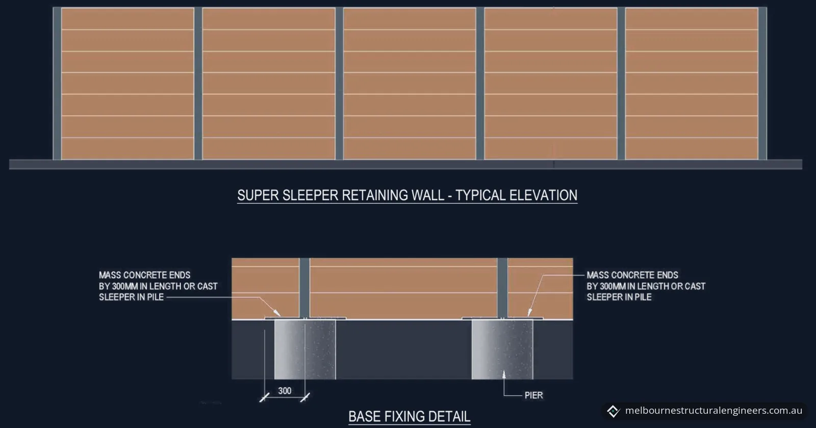
- Wall system. Sleepers stack between steel posts, and each post is set in its own concrete pier. The drawings call them super sleepers, typically 2000 mm long, with the sleeper size as per the supplier.
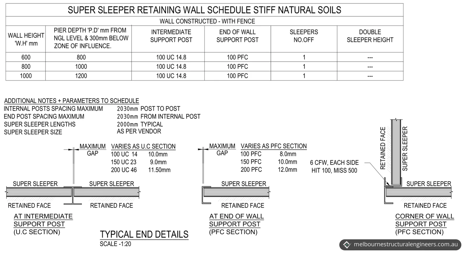
- Posts. Intermediate posts are 100 UC 14.8 universal column sections and end-of-wall posts are 100 PFC parallel flange channels, for all three scheduled wall heights. Internal posts are no more than 2030 mm apart, and an end post is no more than 2030 mm from the internal post next to it.
- End details. UC posts take the sleeper ends at intermediate supports, and PFC posts at the wall ends and at the corner, where the return meets the main run.
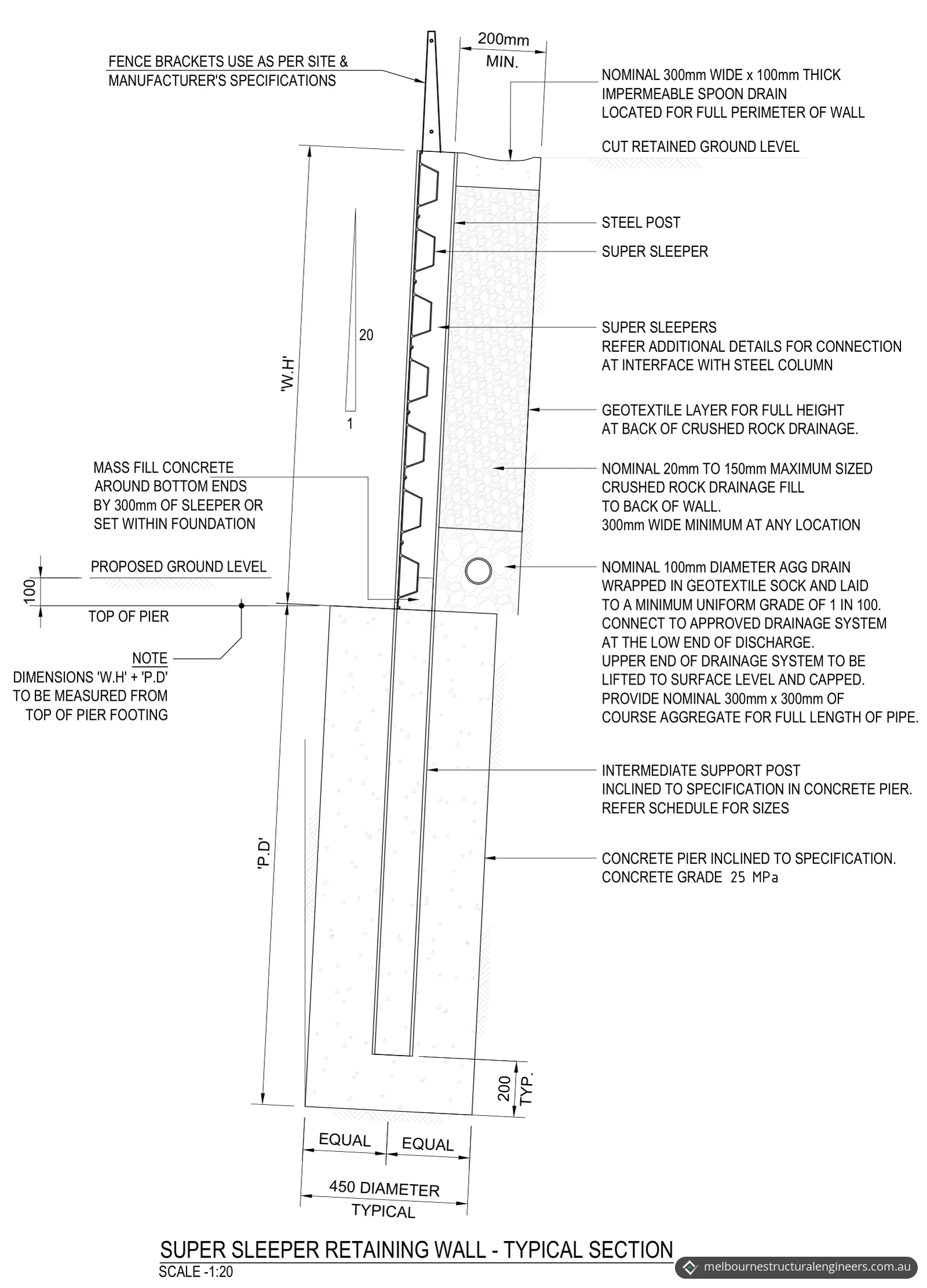
- Piers. The piers are 450 mm in diameter, in 25 MPa concrete, with scheduled depths of 800, 1000 and 1200 mm for walls 600, 800 and 1000 mm high. The posts and piers are inclined to specification, and the typical section draws the wall raked back towards the retained ground. The post stops a typical 200 mm above the base of the pier, and the top of the pier sits 100 mm below the proposed ground level.
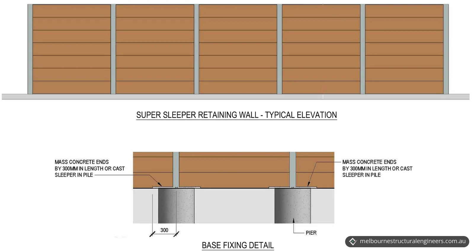
- Sleeper base. At the bottom of the wall, the sleeper ends are surrounded with mass concrete for 300 mm of their length, or the sleeper is cast into the pier.
- Fence. The schedule is for a wall built with a fence. The fence fixes to the top of the steel posts with brackets, used as per the site and the manufacturer's specifications.
- Drainage. Behind the sleepers is crushed rock drainage fill, nominally 20 mm to 150 mm maximum size and at least 300 mm wide at any point, with a geotextile layer for its full height at the back. A nominal 100 mm ag drain in a geotextile sock is laid to a minimum uniform grade of 1 in 100, with nominally 300 x 300 mm of coarse aggregate for the full length of the pipe. It connects to an approved drainage system at its low end, and its upper end is brought up to the surface and capped.
- Spoon drain. An impermeable spoon drain, nominally 300 mm wide and 100 mm thick, runs along the full perimeter of the wall.
The wall schedule, for a wall built with a fence on stiff natural soils:
| Wall height (W.H) | Pier depth (P.D) | Intermediate post | End-of-wall post |
|---|---|---|---|
| 600 mm | 800 mm | 100 UC 14.8 | 100 PFC |
| 800 mm | 1000 mm | 100 UC 14.8 | 100 PFC |
| 1000 mm | 1200 mm | 100 UC 14.8 | 100 PFC |
How the piers stay clear of the sewer
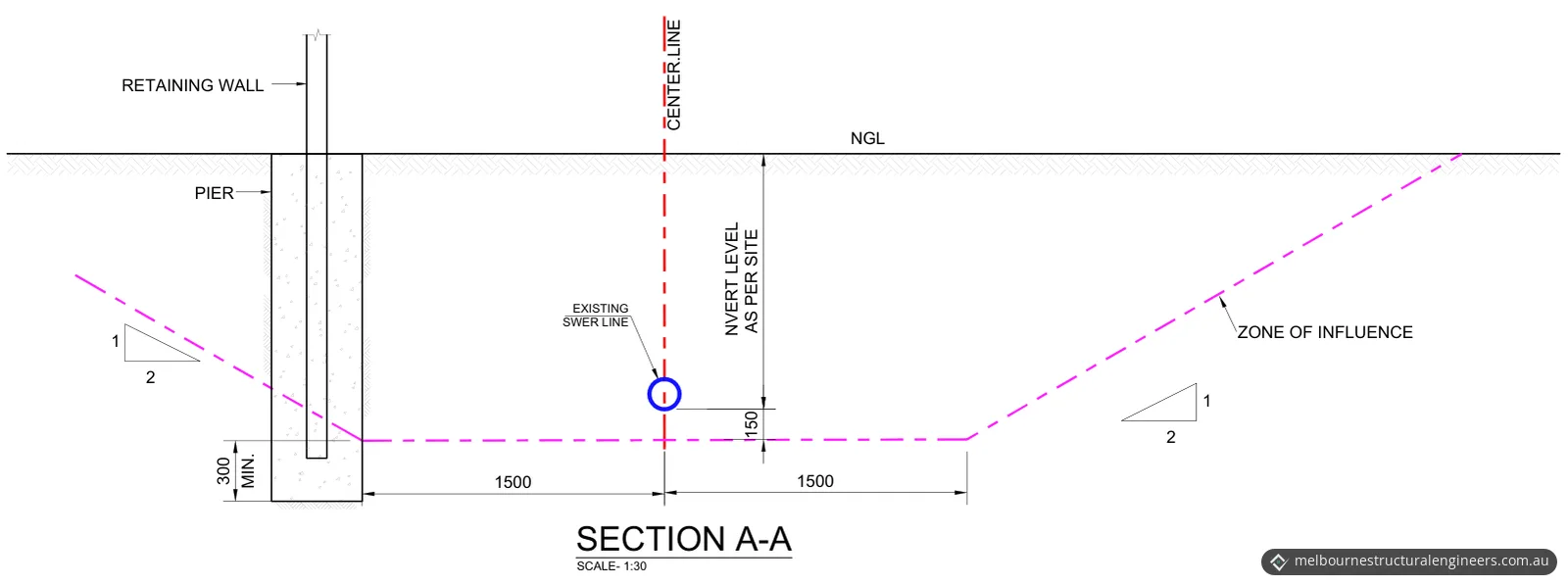
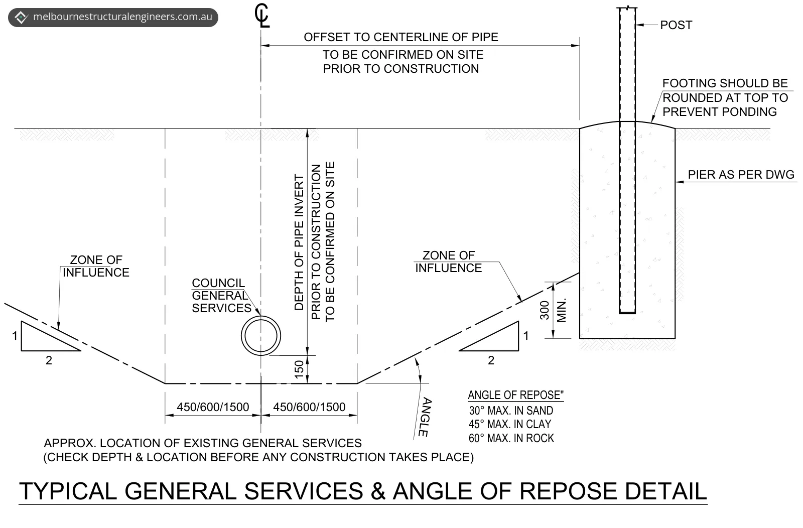
The zone of influence sheet shows how deep each pier must go to reach below the existing sewer line's zone of influence. The schedule's pier depths are tied to it too: each pier goes at least 300 mm below the zone of influence.
- Section A-A. The zone of influence starts 150 mm below the sewer pipe and runs 1500 mm either side of the pipe's centreline. From there it rises at 1 vertical to 2 horizontal up to natural ground level. The retaining wall pier extends at least 300 mm below that line.
- Pipe position. Section A-A gives the sewer's invert level as per site. The typical detail says the pipe's offset from the wall and its invert depth are to be confirmed on site before construction, and the location and depth of existing services checked before any construction takes place.
- Typical detail. In the general services detail, the flat base of the zone extends 450, 600 or 1500 mm either side of the pipe's centreline, and its sides are limited by the angle of repose: 30° at most in sand, 45° in clay and 60° in rock. The top of the footing is rounded to prevent ponding.
What has to be confirmed on site
The design depends on the ground and the sewer, so the drawings list what the builder and the client must check:
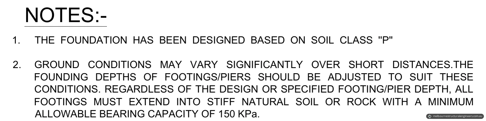
- Soil class. The foundation is designed for a Class P soil classification, taken from an existing geotechnical report for the site.
- Founding depth. Ground conditions may vary significantly over short distances, so the founding depths of the piers should be adjusted to suit them. Whatever depth is designed or specified, all footings must extend into stiff natural soil or rock with a minimum allowable bearing capacity of 150 kPa.
- Geotechnical check. The general notes ask the client or their representative to engage a geotechnical consultant to evaluate and verify the foundation soil conditions before construction starts.
- Sewer location. The offset to the pipe's centreline and the depth of its invert are confirmed on site before construction.
- Groundwater. If groundwater is found at the design depth of the piers, the contractor must promptly contact the engineer for advice.
- Dimensions. The builder confirms all dimensions, existing conditions, obstructions and limitations on site before ordering or delivering materials, and reports any discrepancies to the engineer straight away.
The result
The client received the five-sheet drawing set, issued for approval. It gives the builder the pier size and depth, the post sections and spacing, the sleeper base fixing, the fence bracket note and the drainage for each scheduled wall height, and it shows how deep the piers go below the sewer's zone of influence. It also lists the soil, sewer and dimension checks to make before and during construction.
Under the general notes, the drawings are subject to approval by the relevant local authority or council before construction, and no work is to start until written authorisation to proceed has been issued. On completion, if required, the contractor certifies that the as-built works match the approved issued-for-construction drawings and specifications.
Planning a retaining wall near a sewer or boundary in Melbourne's north?
Our retaining wall design service covers walls that support a boundary fence and walls on or near a boundary. Send us the wall's height and length, what sits above and below it, a few photos of the site, any survey, soil report or plans you have, and any request from your council or building surveyor, and we'll give you a fixed quote. Our Craigieburn page covers our work in Craigieburn and the surrounding area, and our service areas page lists the rest of Melbourne and Victoria we cover. For site drainage beyond the wall itself, see civil and stormwater engineering. You can request a quote online or call 03 7048 4006.
Photos and drawings
From the report
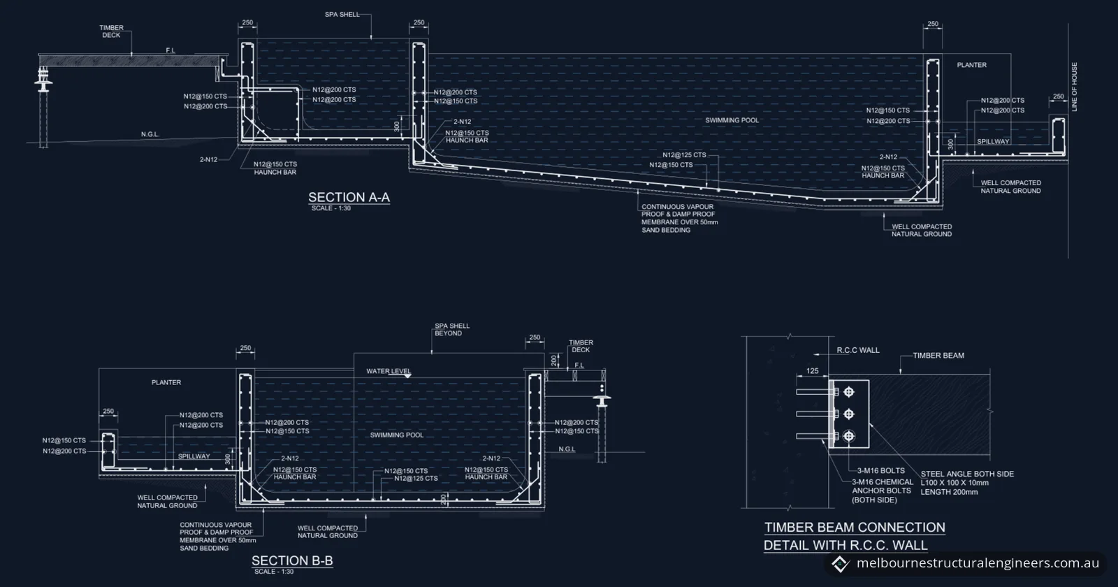
Sample pages from what the client received (personal details removed).
Frequently asked questions
Do I need a building permit for a retaining wall in Victoria?
Not always. Under item 15 of Schedule 3 of the Building Regulations 2018, a retaining wall less than 1 m high is exempt from a building permit, unless it is associated with other building work or with protection of adjoining property. Hume City Council gives the same rule for walls less than 1 metre high, and practice note BP-01, published by the Victorian Building Authority (now the Building and Plumbing Commission), notes that exempt building work may still have to comply with the NCC.
Do I need consent to build near a sewer in Victoria?
It depends on where you build. Regulation 130 of the Building Regulations 2018 requires the report and consent of the relevant service authority for a building permit application to build over an easement vested in that authority. The regulation's note says section 148 of the Water Act 1989 also prohibits building a structure or placing fill without the water authority's consent on land with an easement for water supply, sewerage or drainage, within 5 m laterally of Melbourne Water's works, or within 1 m laterally of any other water supply authority's works.
What does a Class P site mean?
Under Part 4.2 of the NCC Housing Provisions, foundations are classified in accordance with AS 2870. The explanatory Table 4.2.2 describes Class P sites as those with soft soils such as soft clay or silt or loose sands, landslip, mine subsidence, collapsing soils, soils subject to erosion, reactive sites subject to abnormal moisture conditions, or sites that cannot be classified otherwise. For a Class H, E or P site, it says to refer to AS 2870 for design and construction information.